How to Use a Multimeter
Published by Ian Fortey in nauticalknowhow Last updated on January 7, 2022
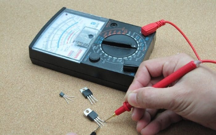
Many of the problems that you will encounter on your vessel are electrical problems. It is because of this that the multimeter is an invaluable tool. With it you can do a lot of troubleshooting and track down potential problems without calling an electrician. I prefer a digital multimeter that gives a more accurate digital readout over the less expensive analog models that have a needle that moves over a set of printed numbers on the dial. You can get a good, dependable multimeter at most marine supply stores or on Amazon for well under $100.00.
Understanding AC Voltage versus DC Voltage
Multimeters can be used to measure voltage (pressure), amperage (flow rate), and Ohms (resistance). These measurements can be made on AC or DC systems. Before using a multimeter, make sure you understand the basics of electricity.
AC , or alternating current, is the same current that you find in your home that is used to turn on your television, lights, etc. This is usually 120 volts and can be dangerous. This same AC current comes to your boat via your shore power cord or an extension cord. You might be simply operating a sander with an extension cord from the dock or, on larger vessels, operating all the appliances and comforts of home via your shore power cord when docked and your generator when underway.
DC , or direct current, is that current supplied by your batteries. This is what starts your engine(s), runs your electronics, your VHF radio, your DC lighting system, running lights, etc. This is generally a 12-volt system, except on larger boats where you may find a 32-volt system.
An important factor when using a multimeter is to make sure that you are using the correct scale depending on whether you are measuring AC or DC. (This should be clearly marked on the face of your multimeter.) If you measure AC current while on a DC scale you could destroy your meter and, worse yet, get a severe shock. If you don’t have at least a working knowledge of the basics don’t attempt to measure AC voltage. Measuring DC voltage is what you’ll mostly want to focus on.
AC and DC systems on boats often share the same electrical panel. Make sure you know which is which and never work on the panel with the AC power still active from the dock.
Let’s review what we can test for with our multimeter.
What Does a Multimeter Measure?
Measuring pressure (voltage): Water pressure is measured by inserting a gauge in the line and comparing the difference to the pressure in the line to the surrounding atmospheric pressure. Because atmospheric pressure is all around us, by leaving one side of the gauge open, the difference can be measured. Voltage is measured in much the same way except the reference point is not atmospheric pressure but ground. The meter cannot measure the difference without being connected to the ground reference point. Thus, we must attach our meter to both the positive and negative (ground) sides of the circuit.
Measuring flow (amperage): To measure water flow, the rate of flow could be measured by inserting a paddle wheel into a pipe and seeing how fast it spins as the water flows through. Your multimeter, using the amperage scale, is the electrical equivalent of the paddle wheel and measures the flow through the circuit.
Measuring resistance (ohms): As water flows (amperage) through a pipe at a regulated pressure (voltage) and this rate of flow is measured, the resistance can be deduced. The same theory is used to measure electrical resistance. The multimeter, when used to measure ohms, uses an internal battery to supply current (amperage) at a carefully regulated pressure (voltage) to the circuit being tested. Using ohm’s law the resistance can be calculated.
Parts of Multimeter
There are a lot of different designs for multimeters but overall you’re getting the same basic product. Without all the bells and whistles that some offer, you have a few standard features that apply across the board.
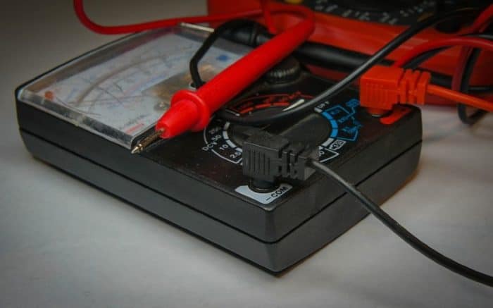
Ports: Every multimeter has ports to connect the probes. You’ll likely see three ports, two that are red and one in the middle that’s black. The black will be labelled “COM.” That means “common” and this is the ground or negative port. Keep in mind that the color is just to help you distinguish between them here and it doesn’t mean anything.
The left port is usually red and will be labelled something like “A” or “10A” or “10Amax.: This is the port for measuring larger currents above 200mA.
On the right is a port that can be labelled mAVΩ or VΩ or something similar. Usually this is where you’ll be plugging the red probe in. It measures any current up to 200mA as well as voltage (V) and resistance (Ω).
Display: This is of course where the data you’re measuring is shown. Fancier multimeters are able to display more information based on whatever the unit you purchased is able to do. In a basic unit, you will have a 4 digit readout including a negative sign. It’s always a good idea to get an illuminated unit so you can read it in the dark.
Dial/Knob: This is the way you can select what the meter is supposed to be measuring. You’ll be able to choose between different currents, resistances and voltages ranging from low to much higher.
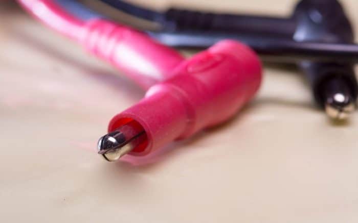
Probes: Multimeter probes don’t follow a universal standard for looks or design, but there’s not a ton of variety between them either. You’ll have a red probe and a black probe. While the parts that plug into the multimeter don’t usually have a lot of difference, they’re typically banana plug style connectors, the actual probe end can vary a lot.
Common probe types include alligator clips which can be squeezed to open and have teeth to attach them to things. Alligator clips are ideal for simply holding your electrical component while you do something else with your hands.
There are also IC hooks which have a tiny grabber end on them. This is for finer work than what you’d do with an alligator clip testing electrically connected parts.
Tweezer probes work like the name says, giving you the ability to grasp and lift small electrical components with tweezer tips as you measure with the multimeter. Obviously you need to keep your hands engaged to use these.
Simple probes are also available that don’t offer any grasping or holding ability, but they do make a connection and measure accurately. You touch these to whatever you’re measuring, get a reading, and then set them down again.
How to Use the Meter to Measure DC Voltage and More
As with any piece of equipment, you should carefully read the manufacturer’s instructions prior to use. Various multimeters have basically the same features but the features may be selected in different ways. Usually, the more you pay the more features you will get. The following methods will be based on a fairly inexpensive generic multimeter.
Although it does not matter which leads from your multimeter you use to test AC current, when testing DC, it is imperative that you use the positive (red) lead on the positive (+) side and the negative or ground lead (black) on the negative (-) or ground side of DC circuits. It is a good idea to get into the habit of using the positive and negative leads consistently even on AC current. Remember, AC current can be very dangerous so you always want to be cautious.
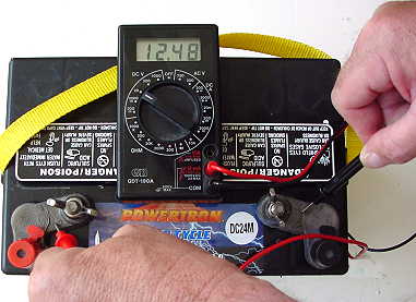
To measure voltage you simply need to touch the positive (red) lead to the positive side of a circuit and the negative (black) lead to ground or the negative side of the circuit. For instance you could put the positive lead on the positive (+) side of your battery and the negative lead on the negative (-) side of your battery to measure the voltage in the battery. A new fully charged battery should read approximately 12.5 volts.
Your meter will have several voltage choices to choose from. For instance mine has, on the ACV(volts) side: 750 and 200. On the DCV side: 200m, 2000m, 20, 200, 1000. Unless your meter has a feature that automatically selects the correct voltage, always start at the highest voltage selection available first. Why? Suppose you have a situation where you have both 120v AC and 240v AC circuits. If you select the 750v option first, you won’t blow out your meter if you mistakenly touch the 240v circuit. Once the voltage is confirmed in the readout you can select the lower range to get a more accurate reading.
What If You Accidentally Reverse Red and Black?
Mistakes when dealing with electricity can be deadly, so it’s good to be cautious. You always want to do things safely. As we’ve said, red is positive and black is negative and this is pretty much universal for all electrical testing. But suppose you do it wrong here. When measuring voltage, if you switch your black and red probes you don’t need to worry. It won’t ruin your reading at all, it will just reverse it.
The multimeter measures voltage in relation to the common probe. So if you reverse them accidentally, your reading will be reversed. If it comes up as -1.8 volts, then it’s actually +1.8 volts.
All that said, you really don’t want to make a mistake like this. It doesn’t matter here, but it can matter elsewhere. Red is positive and black is ground or negative. Save yourself a hassle in the future and keep it in mind.
When Would You Measure Voltage?
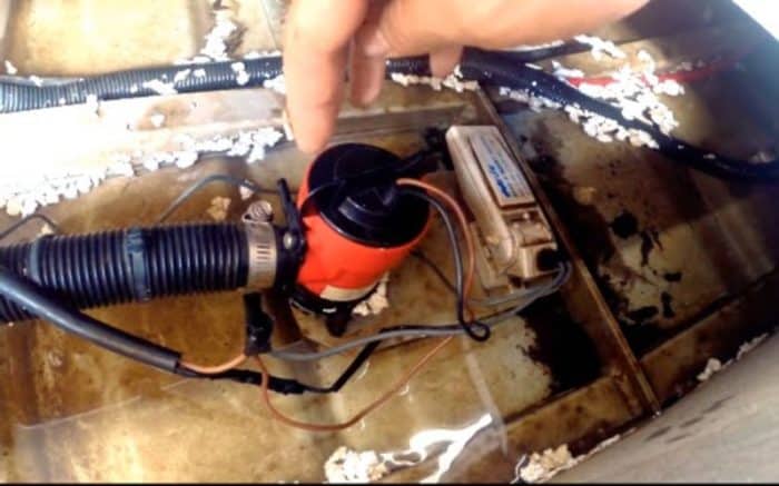
What other situations might prompt you to measure voltage? Let’s say you have an aerator pump in your live well that connects to, and is powered by, your battery. It worked fine last time you went fishing however today you put in the bait, turn on the switch and nothing happens. Do you have enough voltage in your battery to run the pump? You check this and find that you do. Next you use the meter to check the positive (red) and negative (black) wires going into the switch. Hmmm…no voltage. The solution must be that there is a loose or broken wire between the battery and the switch.
Overload Situations
The dial on your multimeter lets you choose a lot of different voltages, currents and resistances. But what if you pick one that’s way out of range? We said earlier you should start high and work your way down. That’s because you’re trying to avoid an overload situation.
If the setting you have picked is too low for the voltage you’re measuring it’s not going to give you a useful reading. Most multimeters display this as the number 1. That means it can’t read what you’re telling it to read and the range is off. In this case, you want to switch to another setting. That’s why it’s best to start high and work down rather than starting low and working up. You get a much clearer picture and can fine tune things more easily that way.
When Would You Measure Amps?
Amperage (current) can be measured (both AC and DC) by connecting the meter in series with the appliance you are measuring. On board you may have many appliances such as water pumps, fans, stereos, radios, electronics, etc. All these items draw current from your battery. These appliances may draw from .5 to 6 or 7 amps. Your battery, however, only has so much current that can be drawn before its voltage drops to a point that it will not run anything.
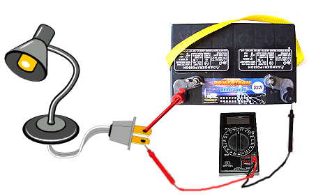
Most appliances will have ratings on them that tell the voltage required and the amps or current that they use. However, let’s say you bought a 12-volt lamp at a marine yard sale that has no rating listed. You want to find out how many amps the lamp will draw. By connecting the meter in series with the lamps wiring and your battery you can measure the amperage that the lamp will use.
When Would You Measure Ohms?

You can measure resistance in Ohms using your multimeter. Make sure that you only measure resistance on circuits that are free from a power source or you will blow your meter. The meter itself supplies the power source from its internal battery. This battery will discharge over time and may need to be replaced. Why would you want to measure resistance? Basically when you are measuring resistance you are measuring to see if you have a complete circuit. When you place the meter in a circuit that has been disconnected from its power source you can tell if the circuit is complete. You can start by checking the circuit in the meter itself. Turn the selector switch to the area labeled OHM. Depending on your meter you may get a display of the number 1 or the infinity symbol. This indicates that there is a break in the circuit. Now touch the ends of the positive and negative leads together. Your reading should be zero or very close to zero. But why?
Let’s say you have two light bulbs rolling around in a drawer. You remember that one was burned out and you just threw it in the drawer in order to make sure you got the correct replacement. You got the replacement and threw them both in the drawer thinking you would change them out later. Now you don’t know which one is the bad one and which is good. They are both of the frosted variety so you can’t physically see the element to see if it is broken in one bulb. You don’t want to do the trial and error test because you just bought this cool multimeter. How do you identify the good bulb? You can use the multimeter to measure the resistance to find which one has an open circuit. This would be the bad one.
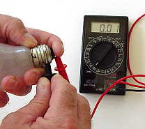
Good Bulb
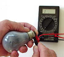
Bad Bulb
Turn the meter to the OHM position. Put the one lead on the bottom part of one of the bulbs. This is the part that touches the contact in the middle of the socket. Then, put the other lead on the metal side of the bulb. This is the part that screws into the socket. Your multimeter changes from 1 to 0 or perhaps 0.01 which mine did. This means you have a closed circuit and you have just tested the good bulb.
Other uses of measuring resistance might be to check a pump that has stopped working. You have voltage to the pump but it does not run. You can test its integrity by measuring resistance. If you place the meter across the circuit (remember to turn off the power) by placing the positive (red) lead on the positive (red) wire going into the pump and the negative (black) lead on the negative (black) or ground wire going into the pump you will be measuring the resistance. If the meter reads 1 or the infinity symbol you know that there is a short in the pump wiring.
A continuity setting lets you test resistances between two points. If there is very low resistance the probe will sound a tone.
Multimeter Features to Look For
If you aren’t using a multimeter as part of your job, you probably don’t need the best one on the market. But you may not want to go for the cheapest one, either. You want a reliable tool. We said earlier one that is illuminated or has an LCD display is a good idea. There are some other good features to invest in also.
Check the quality of the probes if possible. Flimsy ones that fall apart too fast will obviously not be good. If it offers a few kinds of probes, that’s good too.
Check the knob. There should be a distinct transition from one setting to the next so it clicks and sets to each new voltage or resistance. If the knob smoothly moves from one to the next it can sometimes be hard to tell if you’re exactly on the right setting, and that could be bad.
Autoranging is a feature that is used to automatically find the voltage/current/resistance without you having to set it manually. This is a nice feature, but certainly not a must have.
The Bottom Line
A multimeter is invaluable for anyone dealing with electrical systems, but you don’t need to sweat over becoming an amateur electrician at all. Get a good quality unit and familiarize yourself with its functions. Play around with it at home and learn how to read it and what the readings mean. Youtube is a great place to learn the ins and outs. Once you know what you’re doing, fixing any electrical issues on your vessel will be that much easier.
Categories: nauticalknowhow